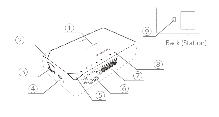
Station Unit
| Name | Description | |
| 1 | Status LED | Illuminates according to power supply and status. |
| 2 | Function2 Button | Used to switch station settings and functions. |
| 3 | Ethernet Port | Used to connect with a switcher such as LiveWedge that can acquire a tally signal via Ethernet. |
| 4 | Micro USB Port | Used for power supply, connect the included AC adapter. |
| 5 | Function1 Button | Used to switch station settings and functions. |
| 6 | GPIO Port | Used to connect with the switcher that outputs a tally signal via GPIO. *A separate connection cable is necessary for connection with the switcher. |
| 7 | Wire Port | Used when connecting with a lamp in wired mode. *Single core pair cable is required. |
| 8 | Tally LED | The status of the tally signal acquired from the switcher is indicated by the LED. |
| 9 | DIP Switch | Used to switch station settings. |
Lamp Unit

| Name | Description | |
| 1 | Power Button | Press and hold to switch the power on or off. |
| 2 | Function Button | Used to switch lamp settings and functions. |
| 3 | Status LED | Illuminates according to power supply and status. |
| 4 | Tally lamp (Front/Back) | Illuminates when the tally signal set on the lamp is acquired from the switcher. |
| 5 | Wire Port | Used when connecting with the station in wired mode. *Single core pair cable is required. |
| 6 | GPIO Port | Tally signal is output as GPIO. For details, refer to “Lamp GPIO output“. |
| 7 | Micro USB Port | Used for power supply and battery charging. |
| 8 | Tripod Hole | Used when attaching to a tripod, etc. |
| 9 | DIP Switch | Used to switch lamp settings. |